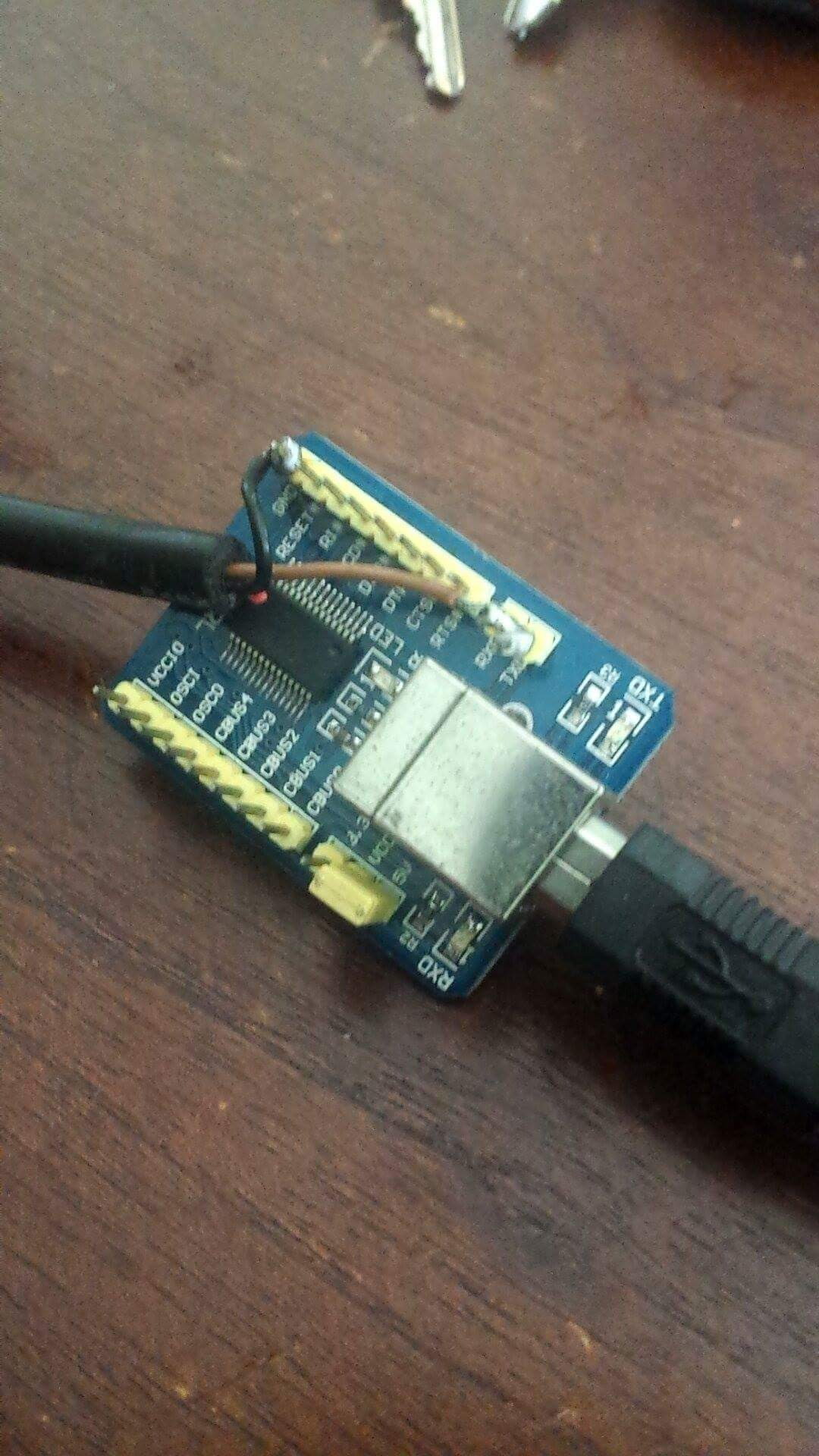

What is aldaldl cables used for? ALDL Cables main purpose is for diagnostics, to perform engine and transmission diagnostics to read live data and fault codes.
#Diy aldl cable diagram serial
How many pins does an ALDL cable have? You can buy an ALDL Cable with an OBD1 12 pin connector shell, or OBD2 style 16 pin connector shell, or a cable with just a bare male pin, to plug into your cars female connector serial data pin location (pin M or E or 9 on the diagrams above).

Unlike the OBD-I connector, which was found under the hood of the vehicle, the OBD-II connector is located on the drivers side of the passenger compartment near the center console. On the standard 12 pin OBDI connector, this will usually be pin M on the 8192 baud rate cars, or pin E on 160 baud rate US domestic cars. The OBD-II specification provides for a standartized hardware interface - the female 16-pin (2x8) J1962 connector. Where do I plug in the ALDL cable? If you have the bare pin cable, you will have to look under your dash to plug the male pin from the ALDL cable into the correct female pin in the cars connector. BLOCKS HIGHLIGHTED LIKE THIS, ARE WIRES THAT ARE NEEDED, AND GO TO EXTERNAL CONNECTION FOR STAND ALONE I have also highlighted the 6 wires used to connect to the gas pedal. Should be similar for 4.8L 6.2L applications. The USB-ALDL Cable is capable of the inserting a 10K resistor across pins A&B of the ALDL connector to initiate communication on some 160 baud vehicles. Below are the ECM Connectors for 2008 vortec 5.3L harness.
#Diy aldl cable diagram how to
Info about How To Make Aldl Cable How does the USB-ALDL cable work? The USB-ALDL Cable is capable of receiving data on ALDL pins D, E, or M.


 0 kommentar(er)
